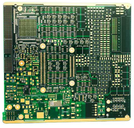
Here is a Rigid Pcb Supplier talking about Commonly used inverter temperature detection circuit.
If you have any idea about Buried PCB Board, welcome to contact us and discuss.

The temperature detection circuit of common IGBT modules is mostly caused by the internal or external temperature sensor of the module (mostly a negative temperature coefficient thermistor), and a voltage divider circuit of +5V is formed in series with the resistor, thereby converting the temperature change signal into a voltage signal. Directly or after being processed by a voltage follower, it is sent to the MCU pin. The detection signal is an analog voltage signal.
The module temperature detection circuit of the low-power inverter is composed of a temperature sensor and a 555 time-base circuit to form a multi-stable (also called multi-vibrator) circuit. The low-level width of the 3-pin output pulse represents a temperature signal. The temperature detection signal is obtained by D-A conversion of the subsequent stage circuit (MCU).
C37, C38 charging time is determined by R2, D32, the time constant is small, corresponding to the high-level width of the 3-pin output pulse; the discharge time of C37, C38 is determined by the parallel value of RT, R3, the time constant is large, corresponding to 3 The low-level width of the pin output pulse.
Address of Plant
PCB Factory:
A1 Building, B Zone, Ditang Industrial Zone, Ditang Road, Shajing Street, Bao'an District, Shenzhen, China
PCBA Factory:
4/F, Building 21, No. 46 Xinye Road, Yonghe Development Zone, Huangpu District, Guangzhou, China
Office Address:
Room 2201-03 & 2206, Building 1, Changfeng International, No. 96, Li Xin 12 Road, Zengcheng District, Guangzhou City, Guangdong Province, China.